You might have to google "toothbrush bot"...
Anyway, I had plenty of bits lying around, so I eventually made a start. I'll warn you now, don't expect anything too impressive - this was my first attempt at anything like this :)
So, I took an old electrical panel cover, drilled a few holes in it and mounted a stepper motor either side. I had a couple of vacuum suckers left over from a previous work project, and I thought they might work as wheels, so after drilling out some bolts to act as axles, I mounted them to the motors. I then glued a couple of rounded nuts to the bottom of the tray to act as skids. It wasn't much, but it was a start.
As usual, click any image for a larger version.

It's upside down here...
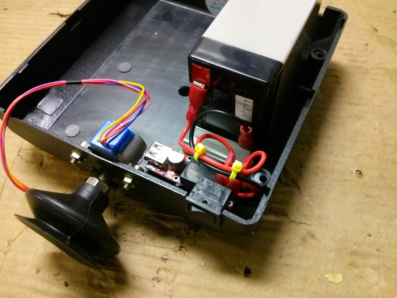
Next step was to find a power source. The Raspberry Pi requires 5 volts, as do the stepper motors, but the more common battery voltages are 1.5V (or multiples of it), 6V or 12V. I had a 6 Volt 4 Ah battery in my drawer, but it was (a)quite heavy and (b)the wrong voltage. The voltage wasn't really an issue; simple voltage regulators are quite cheap (I picked one up from eBay for about £3) but the weight was a bit of a concern. I decided to build the vehicle around this power source, with a view to swapping it out later to a lighter one.
The next couple of pictures show me testing the battery, then testing the output voltage after passing the supply through a regulator. This particular regulator will accept 6V - 42V and give a steady output of 5V at 3A (3 Amps should be more than enough to power an RPi, a WiFi dongle and a couple of small motors). [He said, hopefully.]
The next couple of pictures show me testing the battery, then testing the output voltage after passing the supply through a regulator. This particular regulator will accept 6V - 42V and give a steady output of 5V at 3A (3 Amps should be more than enough to power an RPi, a WiFi dongle and a couple of small motors). [He said, hopefully.]


6.368 Volts direct from the battery, 4.988 Volts through the regulator.
Notice also that the voltage regulator has a USB output. This wasn't ideal for this particular project (you'll find out why later in this post) but it was so cheap it was worth the extra hassle.
OK, so that's our power supply sorted, although I am still worried about the weight. Anyway, I used some self-adhesive plastic mini-trunking (that was all I had available) to stop the battery from slipping around in the tray.

Does it look like a robot yet?
I then mounted a small switch (stolen from a combi-boiler I recently had ripped out) which would act as a main power isolator. I didn't fancy the idea of pulling the connectors off the battery every time I wanted to power down. This switch just breaks the positive supply lead to the voltage regulator.
Mini cable ties are cute and awesome :)
Next up were the actual electronics. There wasn't enough space to lay everything out side by side, so after messing about with designs I decided to raise the RPi above the stepper driver boards. Aside from space saving, this also gives access to the USB ports, one of which will be used for the WiFi dongle. It also allows removal of the MicroSD card from the Rpi, should I bugger something up. Which is likely.

Stepper motor driver boards installed
The RPi itself is raised on pillars, although it doesn't look like it in this photo. The pillars are made from those little nuts either side of a VGA connector that always seem to unscrew themselves. Little bastards.

Totally wonky, but solidly mounted
OK, that was all the essential hardware in place, now for the wiring. I connected the stepper motor flying leads to the driver boards and tucked the wiring in place. Then I attached the power leads to the driver boards, and stripped the other ends. Unlike previous experiments, this time I'm not powering the stepper motors from the RPi itself, I'm powering them directly from the voltage regulator. This means there will be a lot less load on that all-important surface mounted fuse. All I intend to power from the RPi itself (at the moment) is the WiFi dongle. Finally, I connected some jumper leads to the driver boards and it looked something like this...

It's getting crowded already
It was time to wire up the power leads. To do this, I cut a USB lead in half and stripped the cables. We only need to use two of the four cores (Red and Black, the other two are for data - which we aren't using here). I plugged the large USB plug into the voltage regulator output, and ran the stripped ends into a small terminal block. I stripped the other end of the USB lead, connected those to the terminal block and plugged the small USB plug into the RPi. Why bother cutting the USB lead I hear you ask? Well, we still need power for the stepper motor driver boards. So the two jumper leads I stripped earlier also went into the terminal block. I then connected the data jumpers from the drivers boards to the RPi GPIO pins.
This is getting busy!

Almost there...
Finally, I tidied up the wiring and added the WiFi dongle to a USB port...

Well it's compact...ish
The next step will be configuration and testing, but that's for the next blog post. For now, I'll sign off with more pictures of G-Bot. Yes, I named it G-Bot. My gamer friends will know why :)


Did I mention that I'm worried about the weight of that battery?...
No comments:
Post a Comment
Please leave a comment...